
Capture the evidence
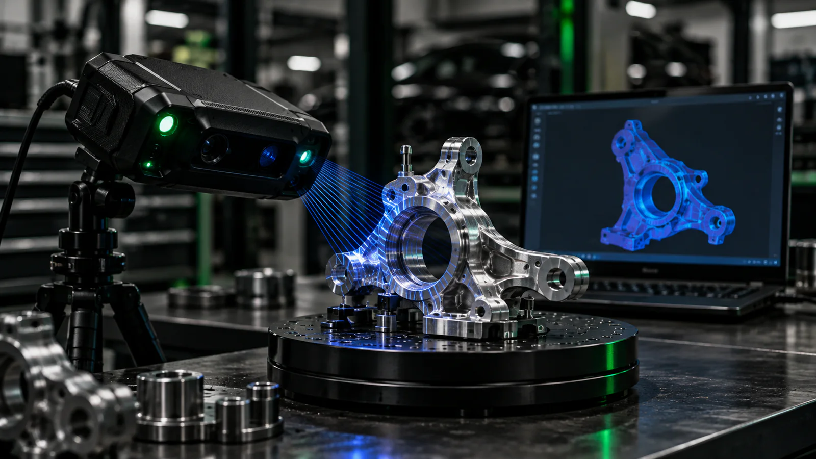
Use 3D scanning, physical measurement, drawings and functional context to understand the component.
03 / Recreate
Recreate damaged, obsolete or undocumented components as clean, manufacturable CAD—using scanning, measurement and engineering judgement.

What we do
The approach
Use 3D scanning, physical measurement, drawings and functional context to understand the component.
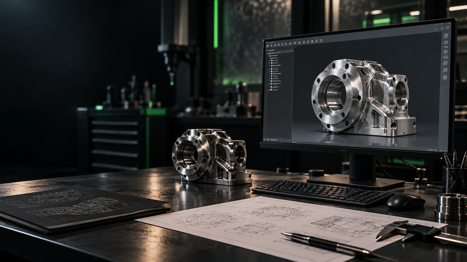
Reconstruct features as controlled CAD rather than simply wrapping a surface around raw scan data.
Resolve critical interfaces, review decisions and create drawings or replacement components to scope.
Have enough information to begin? Start now and add technical details progressively.
Reverse engineer a part ↗Project workflow
Engage True Axis for one stage or carry the project through the complete workflow.
Supply the available component, sample or legacy data.
Capture complex surfaces and critical dimensions.
Rebuild clean, editable design geometry.
Confirm interfaces, wear allowances and intent.
Prepare manufacturing data as required.
Manufacture the recreated component where required.
Project inputs + outputs
Upload the information you already have. True Axis reviews geometry, application, interfaces and inspection needs before confirming scope.
Frequently asked
Usually not. A scan is measured surface evidence. Production-ready CAD typically requires deliberate reconstruction of features, interfaces and design intent.
Potentially. Wear, damage and missing features need engineering interpretation, measurement and context from the assembly before geometry is confirmed.
They are often useful. Interfaces, mounting points and functional clearances can matter as much as the visible shape of the part itself.
Start with what you have
Tell us what you need the component or system to do. We’ll help define the right next step.
Reverse engineer a part ↗