
Raw scan data
A dense measured surface suitable for visual reference, comparison and downstream processing.
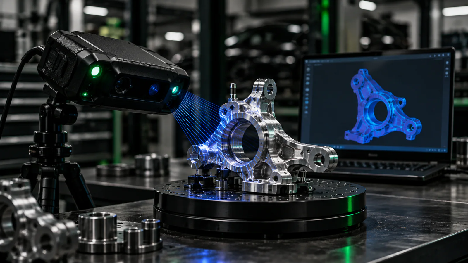
04 / Capture
High-detail digital capture for reverse engineering, comparison, inspection support and component documentation.

What we do
The approach
A dense measured surface suitable for visual reference, comparison and downstream processing.
Aligned and cleaned scan geometry prepared to the agreed deliverable and intended use.
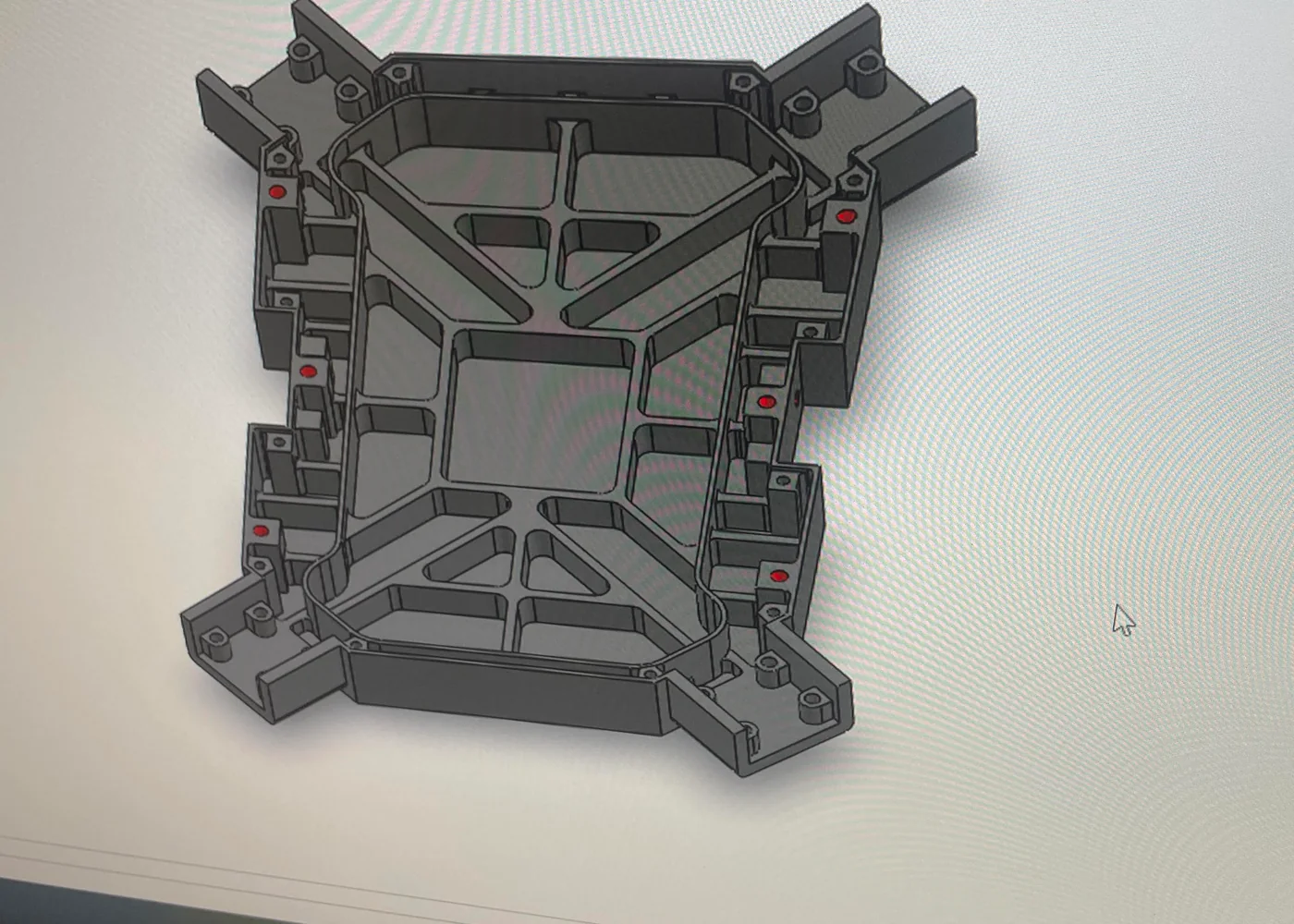
A separately reconstructed model with deliberate features and editable design geometry where required.
Have enough information to begin? Start now and add technical details progressively.
Reverse engineer a part ↗Project workflow
Engage True Axis for one stage or carry the project through the complete workflow.
Clarify how the captured data will be used.
Plan access, references and surface preparation.
Scan the required geometry from suitable positions.
Register the captured data into a coherent model.
Clean and prepare the selected deliverable.
Compare, reconstruct or design from the captured geometry.
Project inputs + outputs
Upload the information you already have. True Axis reviews geometry, application, interfaces and inspection needs before confirming scope.
Frequently asked
Scanning is useful for complex and freeform surfaces, but line of sight, surface condition, access and the required outcome all affect the capture plan.
A mesh represents captured surface points and triangles. CAD uses controlled, editable features and relationships suitable for design changes and manufacturing documentation.
It can support comparison and dimensional investigation when the method and reference data are appropriate. The inspection approach is agreed project by project.
Start with what you have
Tell us what you need the component or system to do. We’ll help define the right next step.
Reverse engineer a part ↗